Scientific Report 971
This report is also available as a PDF document .
Abstract
This paper outlines experimental investigations undertaken on the Belgian high speed rail network to facilitate the validation of a finite element model and to investigate the vibration propagation characteristics of three different earthworks profiles. The sites tested were an embankment, an atgrade section and a cutting and the soil material properties at each site were determined using MASW techniques. Once recorded, the results were compared against those from the numerical model and a high correlation was found.
Regarding the effect of earthworks profiles on vibration levels, vibrations were measured up to 100m from the track and it was found that cuttings produced elevated vibration levels in comparison to the atgrade and embankment cases. Furthermore it was shown that the presence of embankments generated higher frequency content.
Background
High speed rail generates elevated levels of ground borne vibration in comparison to traditional rail. These vibrations can have negative effects on the local environment, particularly in urban areas. Therefore numerical models have been developed to predict these vibrations before potential new lines are constructed. Despite this, many of these models have not been properly validated due to a lack of experimental data (Hung & Yang, 2000). One such model has been developed at the University of Edinburgh, which had also not been validated. The model is a 3D, fully coupled, finite element model, for which more details can be found in (Connolly, Giannopoulos, & Forde, 2013) and (Connolly, Giannopoulos, Fan, Woodward, & Forde, 2013). Therefore the primary aim of this work was to collect data to validate the model. A secondary aim was to investigate the effect of earthworks profiles on vibration levels. A NERC Geophysical Equipment Facility loan consisting of a 24 channel GEODE system and Panasonic Toughbook was secured for this purpose.
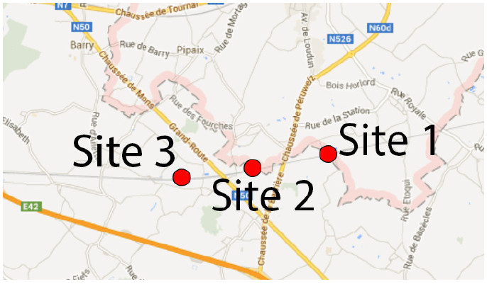
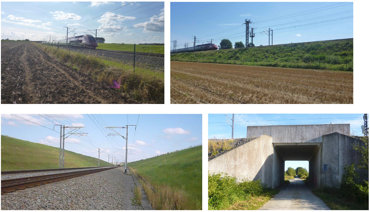
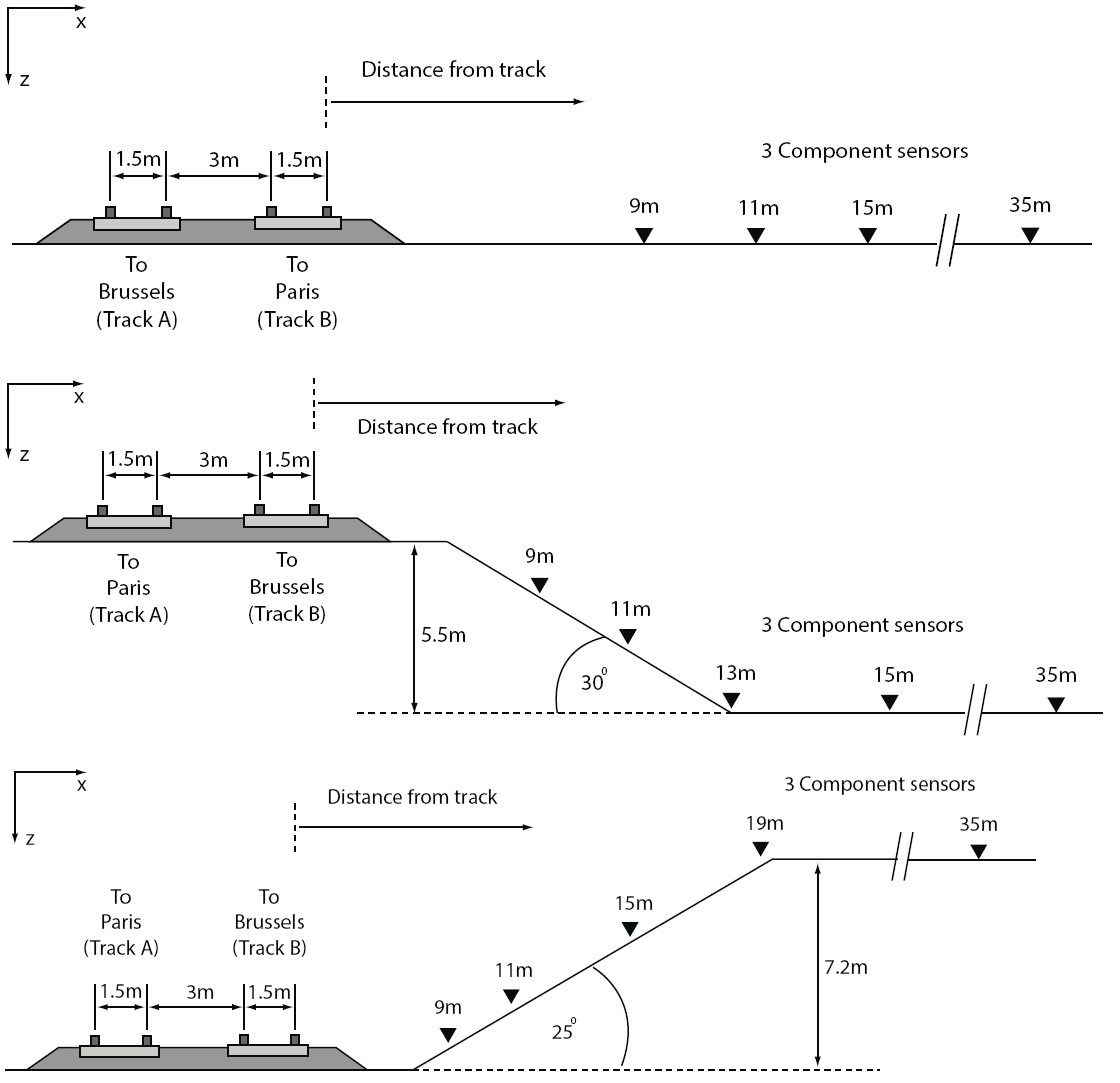
Three tests were performed at three Belgian test sites located near the town of Leuzeen Hainaut (Figure 1 and Table 1). Site 1 was an atgrade site, site 2 was a site with a 5.5m high embankment and site 3 had a 7.2m deep cutting (Figure 2). Three types of high speed locomotive were found to operate on the line: Thalys, TGV and Eurostar.

Survey Procedure
The survey procedure was composed of 2 parts: railway vibration measurement and MASW testing.
Railway vibration measurement
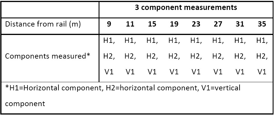
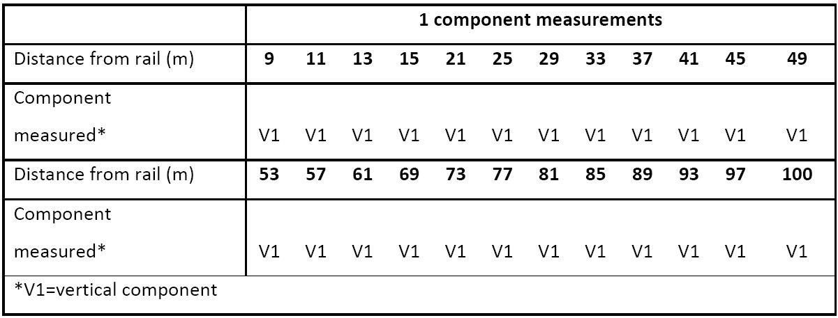
Geophones (Low frequency (4.5Hz), SM6 from www.geophone.com) were placed at distances from the track as outlined in Table 2, Table 3 and Figure 7. Geophones were preferred to accelerometers due to their ruggedness and ability to perform in adverse weather conditions. Three component sensors were used to record vibration levels up to 35m from the track and one component geophones recoded vibrations levels up to 100m from the track. For each passage 16 seconds of vibration were recorded, each with a 2 second negative delay. The GEODE system and Panasonic Toughbook were triggered manually when each train was sufficiently close. Train speeds were determined directly from the geophone response by using signal processing techniques based on isolating the key vehicle frequencies (i.e. wheel and bogie passages).
MASW
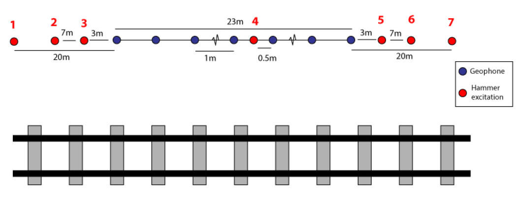
24 one component geophones with 150mm spikes were placed parallel to the track with 1m spacing (Figure 3). 7 excitations were performed using a 12lb PCB 086D50 impact hammer (on an impact plate) with onboard accelerometer. At each site the array was placed far enough away from the track to ensure the results were not contaminated from potential artefacts close to the line, but close enough to ensure that the soil properties were representative of those beneath the track (50m).
Rayleigh damping was required to describe material damping within the FE model, thus making traditional damping calculation techniques challenging. Therefore a curve fitting approach was used. To do so a 2D FE soil model was created with soil layering identical to the profiles described in Figure 5, with receives at identical spacing to those placed during the surface wave experiments. The model was computed for numerous different Rayleigh damping () values until peak particle velocity values for the string of experimental and numerical receivers had strong agreement.
Data quality
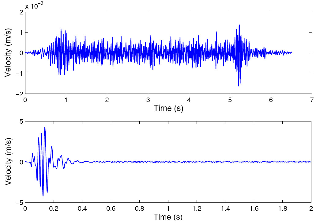
The collected data quality was high for both the surface wave tests and the railway vibration tests. For the railway vibration tests the velocity signals were processed by multiplying the low frequency content by the inverse of the natural characteristics of the geophone. This helped to magnify the low frequency content (i.e. <4.5Hz). An example of a velocity time history for both the surface wave and train passage experiments can be seen in Figure 4.
Processing and modelling
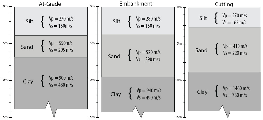
Postprocessing was performed using Geopsy (Wathelet, 2008a) and Dinver (Wathelet, 2008b). Geopsy was used to plot the dispersion curves in the frequencywavenumber domain and then Dinver was used to perform the inversion. The theoretical and experimental dispersion curves were found to agree well and the error was low. Furthermore, checks with local borehole information showed a high correlation with the experimental results. The resulting ground wave speed profiles are shown in Figure 5. Due to FE modelling constraints, the ground profiles were only required to a depth of 15m. It can be noticed that all three profiles are relatively similar. This permitted comparison between vibration records at all three sites. During recording, high gain was used to prevent clipping of the original signal.
For each train passage record, velocity amplitudes were of key importance so the gain was removed during postprocessing.
Interpretation to date
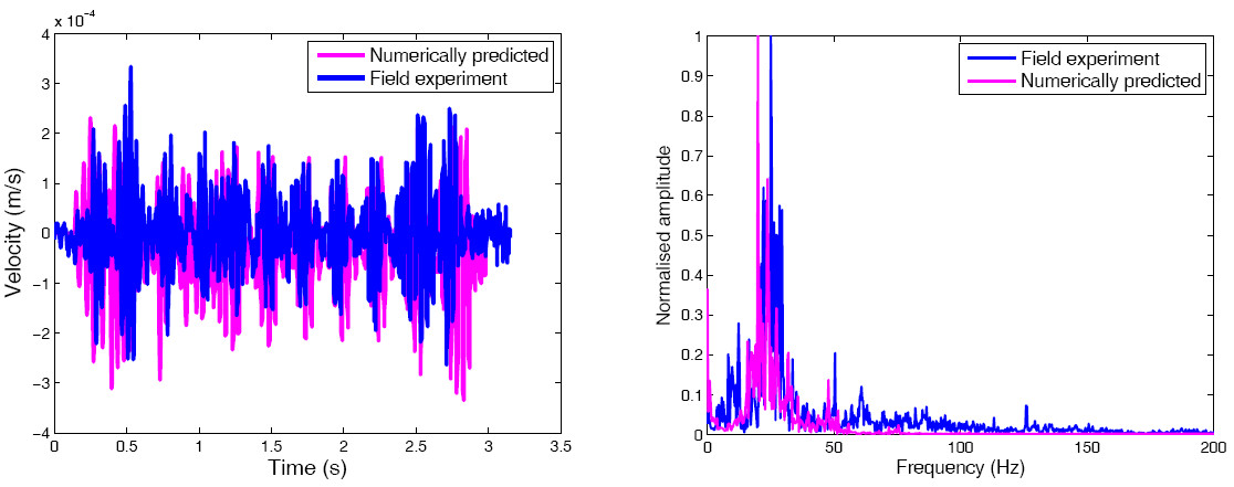
After the soil properties had been determined, the numerical model was adapted to replicate the soil profiles. The atgrade site was first recreated and a comparison between experimental and numerical results is presented in Figure 6. It can be seen that the numerical model was able to accurately predict the velocity time histories and frequency content. Work is currently being undertaken to validate embankment and cutting numerical models.
Preliminary findings
In addition to numerical model validation, analysis of the field results revealed that:
-
Vertical component vibration levels are dominant in comparison to horizontal.
-
Cuttings track sections generate greater ground vibration in comparison to fill and atgrade and embankments.
-
Tracks on embankment generate higher frequency vibrations in comparison to those at grade. Tracks in cutting also generate lower frequency content than embankments but more higher frequency content than atgrade.
-
The higher frequency vibrations components generated by railway lines are damped faster than the lower frequency ones.
-
Thalys, TGV and Eurostar trains have similar setup characteristics and thus cause similar vibration levels.
Conclusions and recommendations
Experimental investigations were performed on an embankment, an atgrade and a cutting railway line on the Belgian high speed rail network. The investigations consisted of the measurement of ground borne vibration levels generated during train passage, and multichannel analysis of surface wave experiments.
The surface wave data was processed to obtain 1D ground profile information for each site and all three sites were found to have similar soil properties. The results were used to recreate a finite element based on the atgrade test site. The model was shown to have high accuracy prediction capabilities.
Finally, the results were also used to investigate the effect of embankments and cuttings on vibration characteristics. It was found that embankments generate a greater level of high frequency content in comparison to atgrade and cutting sections. Furthermore, cuttings generate higher amplitude vibrations in comparison to embankment and atgrade sections.
Acknowledgements
The authors wish to thank NERC and EPSRC for the loan of equipment and funding respectively, without which, this research could not have been undertaken. Additionally the University of Edinburgh, the Université de Mons and Heriot Watt University are also acknowledged for their support and resources provided.
Instrument deployment details
Awards
Scottish Geotechnical group poster presentation cup ‐ https://www.see.ed.ac.uk/drupal/node/598
Publications
Journal papers
Connolly, D., Giannopoulos, A., Fan, W., Woodward, P. K., & Forde, M. C. (2013). Optimising low acoustic impedance back‐fill material wave barrier dimensions to shield structures from ground borne high speed rail vibrations. Construction and Building Materials, 44, 557–564. doi:10.1016/j.conbuildmat.2013.03.034 (Impact factor = 2.3)
Connolly, D.P, Giannopoulos, a., Fan, W., Woodward, P. K., & Forde, M. C. (2013). High speed rail – vibration issues. High Speed Rail – special issue in Construction and Building Materials (under submission)
Kouroussis, G., Connolly, D.P, Verlinden, O., & Forde, M. C. (2013). Remote calculation of train speeds using ground vibrations. Journal of Rail and Rapid Transit (under submission)
Conference papers
Kouroussis, G., Connolly, D.P, Forde, M., Verlinden, O., (2013). An experimental study of embankment conditions on high speed railway ground vibrations. International congress of sound and vibration 2013, Bangkok, Thailand.
Kouroussis, G., Connolly, D.P, Forde, M., Verlinden, O., (2013). An experimental analysis of embankment vibrations due to high speed rail. Railway Engineering 2013, London, UK.
D.P. Connolly, Peters, J., Sim, A., Fan., W., Giannopoulos, A., Forde, M.C. (2013). Significantly reducing environmental assessment costs on new rail lines using an innovative vibration prediction tool. Railway Engineering 2013, London, UK.
References
Connolly, D., Giannopoulos, a., Fan, W., Woodward, P. K., & Forde, M. C. (2013). Optimising low acoustic impedance backfill material wave barrier dimensions to shield structures from ground borne high speed rail vibrations. Construction and Building Materials, 44, 557 564. doi:10.1016/j.conbuildmat.2013.03.034
Connolly, D., Giannopoulos, A., & Forde, M. . (2013). Numerical modelling of ground borne vibrations from high speed rail lines on embankments. Soil Dynamics and Earthquake Engineering, 46, 13 19. doi:10.1016/j.soildyn.2012.12.003
Hung, H., & Yang, Y. (2000). A Review of Researches on GroundBorne Vibrations with emphasis on those induced by trains. Proceedings of the National Science Council, 25(1), 1 16. doi:10.1260/136943306777641887
Wathelet, M. (2008a). www.Geopsy.org.
Wathelet, M. (2008b). An improved neighborhood algorithm: Parameter conditions and dynamic scaling. Geophysical Research Letters, 35(9), 1 5. doi:10.1029/2008GL033256
